/* Hello World Example This example code is in the Public Domain (or CC0 licensed, at your option.) Unless required by applicable law or agreed to in writing, this software is distributed on an "AS IS" BASIS, WITHOUT WARRANTIES OR CONDITIONS OF ANY KIND, either express or implied. */ #include<stdio.h> #include"sdkconfig.h" #include"freertos/FreeRTOS.h" #include"freertos/task.h" #include"esp_system.h" #include"esp_spi_flash.h"
voidapp_main(void) { printf("Hello world!\n");
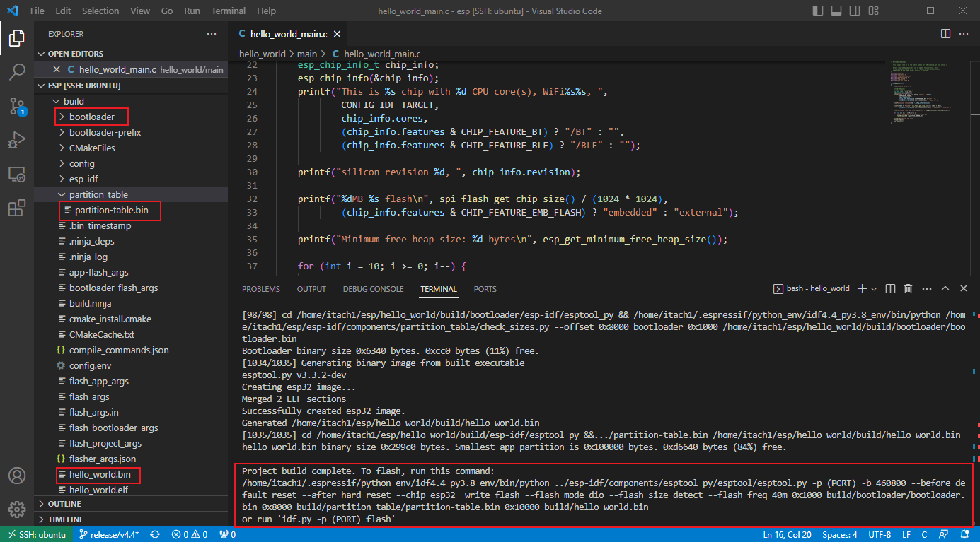
/* Print chip information */ esp_chip_info_t chip_info; esp_chip_info(&chip_info); printf("This is %s chip with %d CPU core(s), WiFi%s%s, ", CONFIG_IDF_TARGET, chip_info.cores, (chip_info.features & CHIP_FEATURE_BT) ? "/BT" : "", (chip_info.features & CHIP_FEATURE_BLE) ? "/BLE" : "");
I (13) boot: ESP-IDF v4.4.2-296-g4b8915d7af-dirty 2nd stage bootloader I (13) boot: compile time 20:55:48 I (13) boot: chip revision: 3 I (17) boot_comm: chip revision: 3, min. bootloader chip revision: 0 I (24) boot.esp32: SPI Speed : 40MHz I (28) boot.esp32: SPI Mode : DIO I (33) boot.esp32: SPI Flash Size : 2MB I (37) boot: Enabling RNG early entropy source... I (43) boot: Partition Table: I (46) boot: ## Label Usage Type ST Offset Length I (54) boot: 0 nvs WiFi data 01 02 00009000 00006000 I (61) boot: 1 phy_init RF data 01 01 0000f000 00001000 I (69) boot: 2 factory factory app 00 00 00010000 00100000 I (76) boot: End of partition table I (80) boot_comm: chip revision: 3, min. application chip revision: 0 I (87) esp_image: segment 0: paddr=00010020 vaddr=3f400020 size=078f4h ( 30964) map I (107) esp_image: segment 1: paddr=0001791c vaddr=3ffb0000 size=02308h ( 8968) load I (111) esp_image: segment 2: paddr=00019c2c vaddr=40080000 size=063ech ( 25580) load I (125) esp_image: segment 3: paddr=00020020 vaddr=400d0020 size=14a30h ( 84528) map I (156) esp_image: segment 4: paddr=00034a58 vaddr=400863ec size=04f28h ( 20264) load I (165) esp_image: segment 5: paddr=00039988 vaddr=50000000 size=00010h ( 16) load I (171) boot: Loaded app from partition at offset 0x10000 I (171) boot: Disabling RNG early entropy source... I (187) cpu_start: Pro cpu up. I (187) cpu_start: Starting app cpu, entry point is 0x40081000 0x40081000: call_start_cpu1 at /home/itach1/esp/esp-idf/components/esp_system/port/cpu_start.c:148
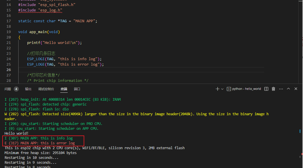
I (0) cpu_start: App cpu up. I (201) cpu_start: Pro cpu start user code I (202) cpu_start: cpu freq: 160000000 I (202) cpu_start: Application information: I (206) cpu_start: Project name: hello_world I (211) cpu_start: App version: 1 I (216) cpu_start: Compile time: Feb 27 2023 20:55:42 I (222) cpu_start: ELF file SHA256: ea5506dd6fe21a17... I (228) cpu_start: ESP-IDF: v4.4.2-296-g4b8915d7af-dirty I (235) heap_init: Initializing. RAM available for dynamic allocation: I (242) heap_init: At 3FFAE6E0 len 00001920 (6 KiB): DRAM I (248) heap_init: At 3FFB2BF0 len 0002D410 (181 KiB): DRAM I (254) heap_init: At 3FFE0440 len 00003AE0 (14 KiB): D/IRAM I (260) heap_init: At 3FFE4350 len 0001BCB0 (111 KiB): D/IRAM I (267) heap_init: At 4008B314 len 00014CEC (83 KiB): IRAM I (274) spi_flash: detected chip: generic I (278) spi_flash: flash io: dio W (282) spi_flash: Detected size(4096k) larger than the size in the binary image header(2048k). Using the size in the binary image header. I (296) cpu_start: Starting scheduler on PRO CPU. I (0) cpu_start: Starting scheduler on APP CPU. Hello world! This is esp32 chip with 2 CPU core(s), WiFi/BT/BLE, silicon revision 3, 2MB external flash Minimum free heap size: 295104 bytes Restarting in 10 seconds... Restarting in 9 seconds... Restarting in 8 seconds... Restarting in 7 seconds... Restarting in 6 seconds... Restarting in 5 seconds... Restarting in 4 seconds... Restarting in 3 seconds... Restarting in 2 seconds...
/* * SPDX-FileCopyrightText: 2015-2021 Espressif Systems (Shanghai) CO LTD * * SPDX-License-Identifier: Apache-2.0 * * This is a STUB FILE HEADER used when compiling ESP-IDF to run tests on the host system. * The header file used normally for ESP-IDF has the same name but is located elsewhere. */ #pragma once
#include<stdint.h> #include<stdio.h>
#include"sdkconfig.h"
#ifdef __cplusplus extern"C" { #endif
#define strlcpy(a, b, c) #define strlcat(a, b, c)
#define heap_caps_malloc(a, b) NULL #define MALLOC_CAP_INTERNAL 0 #define MALLOC_CAP_8BIT 0
#define LOG_LOCAL_LEVEL CONFIG_LOG_DEFAULT_LEVEL
typedefenum { ESP_LOG_NONE, /*!< No log output */ ESP_LOG_ERROR, /*!< Critical errors, software module can not recover on its own */ ESP_LOG_WARN, /*!< Error conditions from which recovery measures have been taken */ ESP_LOG_INFO, /*!< Information messages which describe normal flow of events */ ESP_LOG_DEBUG, /*!< Extra information which is not necessary for normal use (values, pointers, sizes, etc). */ ESP_LOG_VERBOSE /*!< Bigger chunks of debugging information, or frequent messages which can potentially flood the output. */ } esp_log_level_t;
#define LOG_FORMAT(letter, format) LOG_COLOR_ ## letter #letter " (%d) %s: " format LOG_RESET_COLOR "\n"
#define ESP_LOGE( tag, format, ... ) if (LOG_LOCAL_LEVEL >= ESP_LOG_ERROR) { esp_log_write(ESP_LOG_ERROR, tag, LOG_FORMAT(E, format), esp_log_timestamp(), tag, ##__VA_ARGS__); }
#define ESP_LOGW( tag, format, ... ) if (LOG_LOCAL_LEVEL >= ESP_LOG_WARN) { esp_log_write(ESP_LOG_WARN, tag, LOG_FORMAT(W, format), esp_log_timestamp(), tag, ##__VA_ARGS__); }
#define ESP_LOGI( tag, format, ... ) if (LOG_LOCAL_LEVEL >= ESP_LOG_INFO) { esp_log_write(ESP_LOG_INFO, tag, LOG_FORMAT(I, format), esp_log_timestamp(), tag, ##__VA_ARGS__); }
#define ESP_LOGD( tag, format, ... ) if (LOG_LOCAL_LEVEL >= ESP_LOG_DEBUG) { esp_log_write(ESP_LOG_DEBUG, tag, LOG_FORMAT(D, format), esp_log_timestamp(), tag, ##__VA_ARGS__); }
#define ESP_LOGV( tag, format, ... ) if (LOG_LOCAL_LEVEL >= ESP_LOG_VERBOSE) { esp_log_write(ESP_LOG_VERBOSE, tag, LOG_FORMAT(V, format), esp_log_timestamp(), tag, ##__VA_ARGS__); }
// Assume that flash encryption is not enabled. Put here since in partition.c // esp_log.h is included later than esp_flash_encrypt.h. #define esp_flash_encryption_enabled() false
/* Hello World Example This example code is in the Public Domain (or CC0 licensed, at your option.) Unless required by applicable law or agreed to in writing, this software is distributed on an "AS IS" BASIS, WITHOUT WARRANTIES OR CONDITIONS OF ANY KIND, either express or implied. */ #include<stdio.h> #include"sdkconfig.h" #include"freertos/FreeRTOS.h" #include"freertos/task.h" #include"esp_system.h" #include"esp_spi_flash.h" #include"esp_log.h"
/* Timer group-hardware timer example This example code is in the Public Domain (or CC0 licensed, at your option.) Unless required by applicable law or agreed to in writing, this software is distributed on an "AS IS" BASIS, WITHOUT WARRANTIES OR CONDITIONS OF ANY KIND, either express or implied. */ #include<stdio.h> #include"esp_types.h" #include"freertos/FreeRTOS.h" #include"freertos/task.h" #include"freertos/queue.h" #include"driver/periph_ctrl.h" #include"driver/timer.h" #include"esp_log.h"
/* Timer's counter will initially start from value below. Also, if auto_reload is set, this value will be automatically reload on alarm */ timer_set_counter_value(TIMER_GROUP_0, timer_idx, 0x00000000ULL);
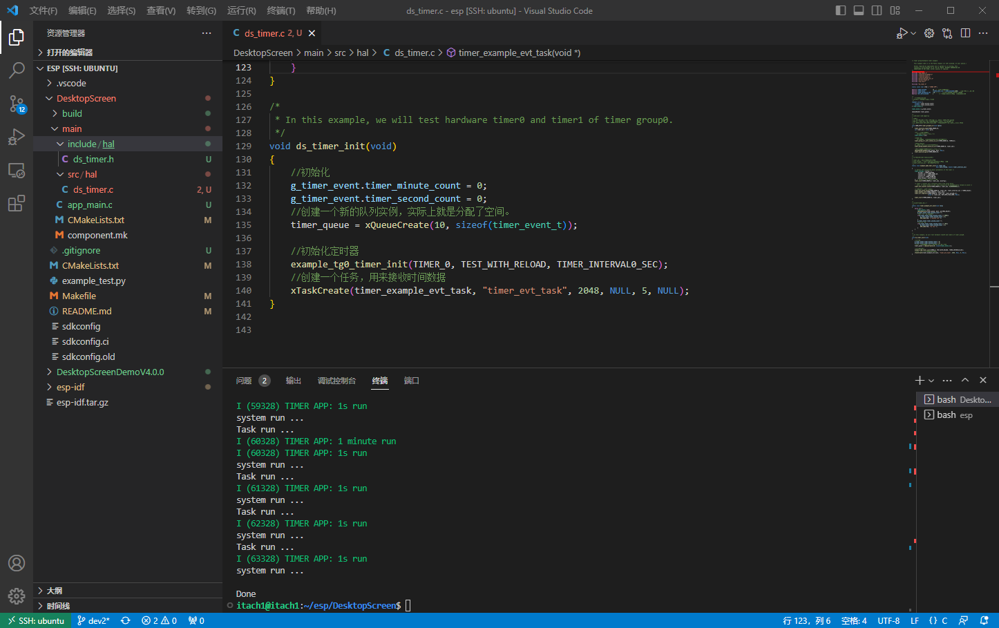
/* * In this example, we will test hardware timer0 and timer1 of timer group0. */ voidds_timer_init(void) { //初始化 g_timer_event.timer_minute_count = 0; g_timer_event.timer_second_count = 0; //创建一个新的队列实例,实际上就是分配了空间。 timer_queue = xQueueCreate(10, sizeof(timer_event_t));
/* HTTP File Server Example This example code is in the Public Domain (or CC0 licensed, at your option.) Unless required by applicable law or agreed to in writing, this software is distributed on an "AS IS" BASIS, WITHOUT WARRANTIES OR CONDITIONS OF ANY KIND, either express or implied. */
/* This example demonstrates how to create file server * using esp_http_server. This file has only startup code. * Look in file_server.c for the implementation */
staticconstchar *TAG="spiffs";
esp_vfs_spiffs_conf_t conf = { .base_path = "/spiffs", .partition_label = NULL, .max_files = 5, // This decides the maximum number of files that can be created on the storage .format_if_mount_failed = true };
/* Function to initialize SPIFFS */ esp_err_tinit_spiffs(void) { ESP_LOGI(TAG, "Initializing SPIFFS");
esp_err_t ret = esp_vfs_spiffs_register(&conf); if (ret != ESP_OK) { if (ret == ESP_FAIL) { ESP_LOGE(TAG, "Failed to mount or format filesystem"); } elseif (ret == ESP_ERR_NOT_FOUND) { ESP_LOGE(TAG, "Failed to find SPIFFS partition"); } else { ESP_LOGE(TAG, "Failed to initialize SPIFFS (%s)", esp_err_to_name(ret)); } return ESP_FAIL; }
size_t total = 0, used = 0; ret = esp_spiffs_info(NULL, &total, &used); if (ret != ESP_OK) { ESP_LOGE(TAG, "Failed to get SPIFFS partition information (%s)", esp_err_to_name(ret)); return ESP_FAIL; }
voidds_spiffs_deinit(){ // All done, unmount partition and disable SPIFFS esp_vfs_spiffs_unregister(conf.partition_label); ESP_LOGI(TAG, "SPIFFS unmounted"); }
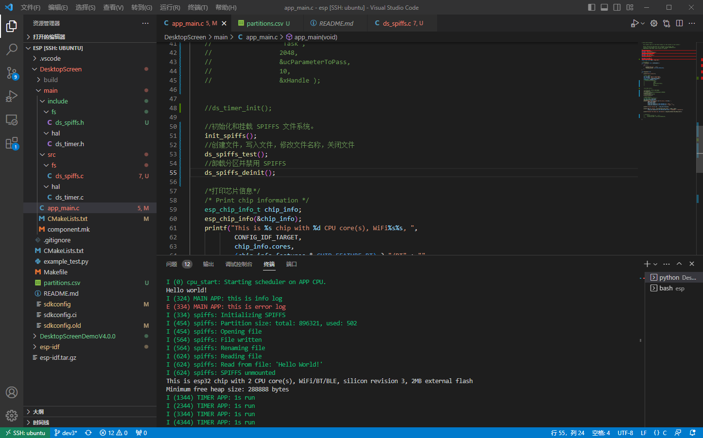
voidds_spiffs_test(){ // Use POSIX and C standard library functions to work with files. // First create a file. ESP_LOGI(TAG, "Opening file"); FILE* f = fopen("/spiffs/hello.txt", "w"); if (f == NULL) { ESP_LOGE(TAG, "Failed to open file for writing"); return; } fprintf(f, "Hello World!\n"); fclose(f); ESP_LOGI(TAG, "File written");
// Check if destination file exists before renaming structstatst; if (stat("/spiffs/foo.txt", &st) == 0) { // Delete it if it exists unlink("/spiffs/foo.txt"); }
// Rename original file ESP_LOGI(TAG, "Renaming file"); if (rename("/spiffs/hello.txt", "/spiffs/foo.txt") != 0) { ESP_LOGE(TAG, "Rename failed"); return; }
// Open renamed file for reading ESP_LOGI(TAG, "Reading file"); f = fopen("/spiffs/foo.txt", "r"); if (f == NULL) { ESP_LOGE(TAG, "Failed to open file for reading"); return; } char line[64]; fgets(line, sizeof(line), f); fclose(f); // strip newline char* pos = strchr(line, '\n'); if (pos) { *pos = '\0'; } ESP_LOGI(TAG, "Read from file: '%s'", line); }
/* Non-Volatile Storage (NVS) Read and Write a Value - Example For other examples please check: https://github.com/espressif/esp-idf/tree/master/examples This example code is in the Public Domain (or CC0 licensed, at your option.) Unless required by applicable law or agreed to in writing, this software is distributed on an "AS IS" BASIS, WITHOUT WARRANTIES OR CONDITIONS OF ANY KIND, either express or implied. */ #include<stdio.h> #include"freertos/FreeRTOS.h" #include"freertos/task.h" #include"esp_system.h" #include"nvs_flash.h" #include"nvs.h" #include"esp_log.h"
//GPIO interrupt type : both rising and falling edge io_conf.intr_type = GPIO_INTR_ANYEDGE; //bit mask of the pins, use GPIO4/5 here io_conf.pin_bit_mask = GPIO_INPUT_PIN_SEL; //set as input mode io_conf.mode = GPIO_MODE_INPUT; //enable pull-up mode io_conf.pull_up_en = 1; gpio_config(&io_conf);
//change gpio intrrupt type for one pin // gpio_set_intr_type(GPIO_INPUT_IO_0, GPIO_INTR_NEGEDGE);
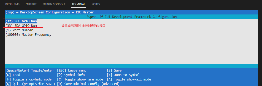
/* i2c - Example For other examples please check: https://github.com/espressif/esp-idf/tree/master/examples See README.md file to get detailed usage of this example. This example code is in the Public Domain (or CC0 licensed, at your option.) Unless required by applicable law or agreed to in writing, this software is distributed on an "AS IS" BASIS, WITHOUT WARRANTIES OR CONDITIONS OF ANY KIND, either express or implied. */ #include<stdio.h> #include"driver/i2c.h" #include"esp_log.h" #include"sdkconfig.h" #include"ds_i2c.h"
/* SPI Master example This example code is in the Public Domain (or CC0 licensed, at your option.) Unless required by applicable law or agreed to in writing, this software is distributed on an "AS IS" BASIS, WITHOUT WARRANTIES OR CONDITIONS OF ANY KIND, either express or implied. */ #include<stdio.h> #include<stdlib.h> #include<string.h> #include"freertos/FreeRTOS.h" #include"freertos/task.h" #include"esp_system.h" #include"driver/spi_master.h" #include"driver/gpio.h"
//To speed up transfers, every SPI transfer sends a bunch of lines. This define specifies how many. More means more memory use, //but less overhead for setting up / finishing transfers. Make sure 240 is dividable by this. #define PARALLEL_LINES 16
spi_device_handle_t spi;
voidspi_send_cmd(constuint8_t cmd) { esp_err_t ret; spi_transaction_t t; ds_gpio_set_screen_dc(0); ds_gpio_set_screen_cs(0); memset(&t, 0, sizeof(t)); //Zero out the transaction // t.flags=SPI_TRANS_USE_TXDATA; t.length=8; //Command is 8 bits t.tx_buffer=&cmd; //The data is the cmd itself t.user=(void*)0; //D/C needs to be set to 0 ret=spi_device_polling_transmit(spi, &t); //Transmit! ds_gpio_set_screen_cs(1); assert(ret==ESP_OK); //Should have had no issues. }
voidspi_send_data(constuint8_t data) { esp_err_t ret; spi_transaction_t t; ds_gpio_set_screen_dc(1); ds_gpio_set_screen_cs(0); memset(&t, 0, sizeof(t)); //Zero out the transaction t.length=8; //Len is in bytes, transaction length is in bits. t.tx_buffer=&data; //Data t.user=(void*)1; //D/C needs to be set to 1 ret=spi_device_polling_transmit(spi, &t); //Transmit! ds_gpio_set_screen_cs(1); assert(ret==ESP_OK); //Should have had no issues. }
//This function is called (in irq context!) just before a transmission starts. It will //set the D/C line to the value indicated in the user field. voidspi_pre_transfer_callback(spi_transaction_t *t) { int dc=(int)t->user; printf("dc callback\n"); ds_gpio_set_screen_dc(dc); }
}; spi_device_interface_config_t devcfg={ .clock_speed_hz=15*1000*1000, //Clock out at 26 MHz .mode=0, //SPI mode 0 .queue_size=7, //We want to be able to queue 7 transactions at a time // .pre_cb=spi_pre_transfer_callback, //Specify pre-transfer callback to handle D/C line }; //Initialize the SPI bus ret=spi_bus_initialize(HSPI_HOST, &buscfg, 0); ESP_ERROR_CHECK(ret); //Attach the LCD to the SPI bus ret=spi_bus_add_device(HSPI_HOST, &devcfg, &spi); ESP_ERROR_CHECK(ret); }
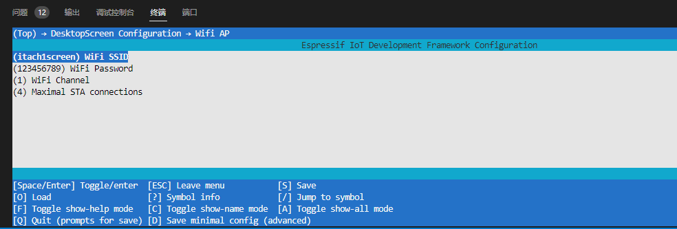
/* WiFi station Example This example code is in the Public Domain (or CC0 licensed, at your option.) Unless required by applicable law or agreed to in writing, this software is distributed on an "AS IS" BASIS, WITHOUT WARRANTIES OR CONDITIONS OF ANY KIND, either express or implied. */ #include<string.h> #include"freertos/FreeRTOS.h" #include"freertos/task.h" #include"freertos/event_groups.h" #include"esp_system.h" #include"esp_wifi.h" #include"esp_event.h" #include"esp_log.h" #include"nvs_flash.h"
/* The examples use WiFi configuration that you can set via project configuration menu If you'd rather not, just change the below entries to strings with the config you want - ie #define EXAMPLE_WIFI_SSID "mywifissid" */ #define EXAMPLE_ESP_WIFI_SSID CONFIG_ESP_WIFI_SSID #define EXAMPLE_ESP_WIFI_PASS CONFIG_ESP_WIFI_PASSWORD #define EXAMPLE_ESP_MAXIMUM_RETRY CONFIG_ESP_MAXIMUM_RETRY
/* FreeRTOS event group to signal when we are connected*/ static EventGroupHandle_t s_wifi_event_group;
/* The event group allows multiple bits for each event, but we only care about two events: * - we are connected to the AP with an IP * - we failed to connect after the maximum amount of retries */ #define WIFI_CONNECTED_BIT BIT0 #define WIFI_FAIL_BIT BIT1
staticconstchar *TAG = "wifi station";
staticint s_retry_num = 0;
staticuint8_t start_status = 0;
staticvoidevent_handler(void* arg, esp_event_base_t event_base, int32_t event_id, void* event_data) { ESP_LOGI(TAG, "-----------%s event %d",event_base,event_id); if (event_base == WIFI_EVENT && event_id == WIFI_EVENT_STA_START) { esp_wifi_connect(); } elseif (event_base == WIFI_EVENT && event_id == WIFI_EVENT_STA_DISCONNECTED) { esp_wifi_connect(); ESP_LOGI(TAG, "retry to connect to the AP"); // if (s_retry_num < EXAMPLE_ESP_MAXIMUM_RETRY) { // esp_wifi_connect(); // s_retry_num++; // ESP_LOGI(TAG, "retry to connect to the AP"); // } else { // xEventGroupSetBits(s_wifi_event_group, WIFI_FAIL_BIT); // } // ESP_LOGI(TAG,"connect to the AP fail"); } elseif (event_base == IP_EVENT && event_id == IP_EVENT_STA_GOT_IP) { ip_event_got_ip_t* event = (ip_event_got_ip_t*) event_data; ESP_LOGI(TAG, "got ip:" IPSTR, IP2STR(&event->ip_info.ip)); s_retry_num = 0; xEventGroupSetBits(s_wifi_event_group, WIFI_CONNECTED_BIT); } }
wifi_config_t wifi_config = { .sta = { // .ssid = EXAMPLE_ESP_WIFI_SSID, // .password = EXAMPLE_ESP_WIFI_PASS, /* Setting a password implies station will connect to all security modes including WEP/WPA. * However these modes are deprecated and not advisable to be used. Incase your Access point * doesn't support WPA2, these mode can be enabled by commenting below line */ .threshold.authmode = WIFI_AUTH_WPA2_PSK,
// 创建事件组 /* Waiting until either the connection is established (WIFI_CONNECTED_BIT) or connection failed for the maximum * number of re-tries (WIFI_FAIL_BIT). The bits are set by event_handler() (see above) */ EventBits_t bits = xEventGroupWaitBits(s_wifi_event_group, WIFI_CONNECTED_BIT | WIFI_FAIL_BIT, pdFALSE, pdFALSE, portMAX_DELAY);
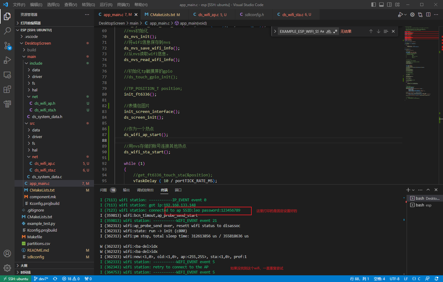
// 连接事件组 /* xEventGroupWaitBits() returns the bits before the call returned, hence we can test which event actually * happened. */ if (bits & WIFI_CONNECTED_BIT) { ESP_LOGI(TAG, "connected to ap SSID:%s password:%s", EXAMPLE_ESP_WIFI_SSID, EXAMPLE_ESP_WIFI_PASS); } elseif (bits & WIFI_FAIL_BIT) { ESP_LOGI(TAG, "Failed to connect to SSID:%s, password:%s", EXAMPLE_ESP_WIFI_SSID, EXAMPLE_ESP_WIFI_PASS); } else { ESP_LOGE(TAG, "UNEXPECTED EVENT"); }
staticesp_err_tsend_wifi_handler(httpd_req_t *req) { int total_len = req->content_len; int cur_len = 0; char *buf = ((struct file_server_data *)(req->user_ctx))->scratch; int received = 0; if (total_len >= SCRATCH_BUFSIZE) { /* Respond with 500 Internal Server Error */ httpd_resp_send_err(req, HTTPD_500_INTERNAL_SERVER_ERROR, "content too long"); return ESP_FAIL; } while (cur_len < total_len) { received = httpd_req_recv(req, buf + cur_len, total_len); if (received <= 0) { /* Respond with 500 Internal Server Error */ httpd_resp_send_err(req, HTTPD_500_INTERNAL_SERVER_ERROR, "Failed to post control value"); return ESP_FAIL; } cur_len += received; }
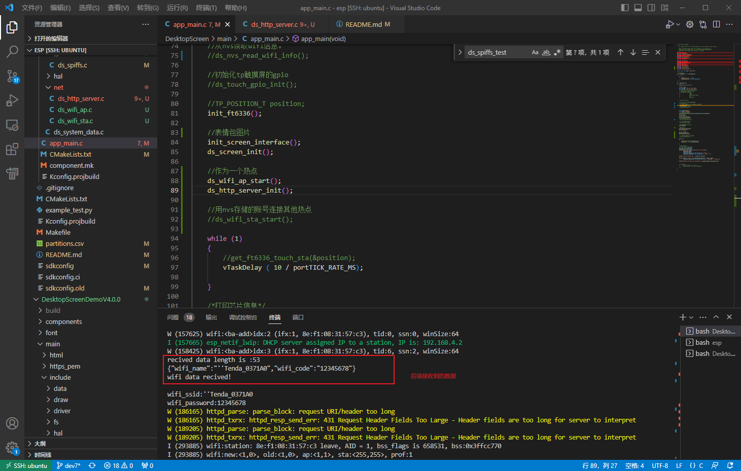
buf[total_len] = '\0'; printf("recived data length is :%d\n",total_len); for (int i = 0; i <total_len ; i++){ putchar(buf[i]); } printf("\r\nwifi data recived!\r\n"); cJSON *root = cJSON_Parse(buf);
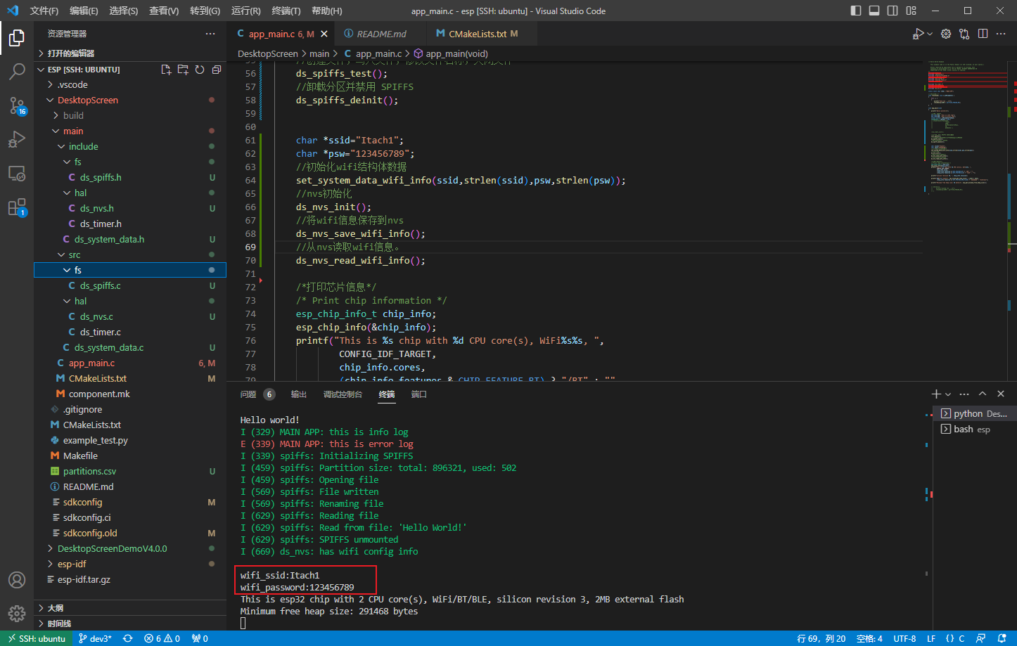
char *ssid = cJSON_GetObjectItem(root, "wifi_name")->valuestring; char *psw = cJSON_GetObjectItem(root, "wifi_code")->valuestring; int ssid_len = strlen(ssid); int psw_len = strlen(psw); set_system_data_wifi_info(ssid,ssid_len,psw ,psw_len); print_system_data_wifi_info(); cJSON_Delete(root); httpd_resp_sendstr(req, "Post control value successfully"); return ESP_OK; }